This weekend coincides with Teachers' Day and Mid-Autumn Festival, so friends went to the beach to admire the moon. When I was driving along the Ocean Parkway of Long Island after get off work, I saw vast seas on both sides, a bright moon in the sky, rough waves, and vast expanse of clear light. It can be said that "the bright moon rises on the sea, and we share this moment with the world." During the festival, I send greetings to my relatives and teachers, and also receive blessings from many classmates and friends from all over the world. It is very touching! This year's summer course just ended last Friday. Due to the explanation of deeper topics (Abel-Jacobi, Riemann-Roch, curved spin structure, spherical transmission theory of specular reflection, etc.), the class period was extended a bit. However, there are still many important topics that were not taught in time, the most important of which is the cohomology theory of pure line bundles and layers.
In the field of engineering, it is often necessary to construct a special geometric or algebraic structure. This kind of structure is easy to establish locally, but it will encounter difficulties when it is extended to the global situation. The cohomology theory of layers is specifically designed to express and solve the global obstacles of this local structure. Although this situation is almost ubiquitous in various engineering fields, due to the highly abstract nature of mathematical theory, traditional engineers currently do not fully understand and apply this thinking method. The classic CAD manual modeling method cannot convert the topology optimized model into a NURBS surface, nor can it directly convert the point cloud obtained by 3D scanning into a spline surface. In particular, surface patches spliced using Boolean operations inevitably have a large number of cracks and overlaps. The bottleneck faced by traditional modeling methods is essentially that they only use local differential geometry and lack the ideas and guidance of global differential geometry.
Inherent flaws of traditional CAD methods
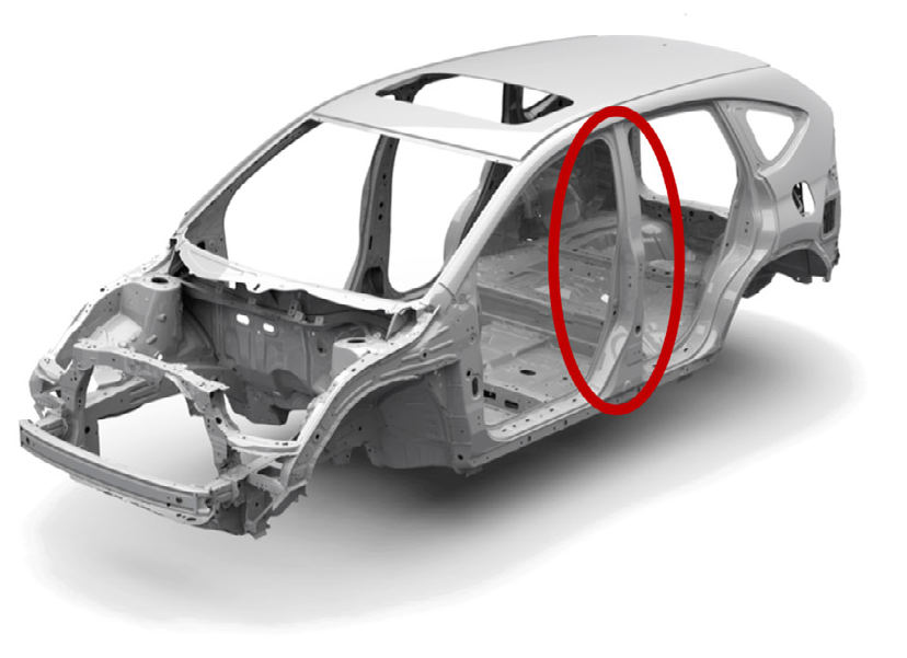
Figure 1. NURBS representation of a Honda car.
In the field of geometric modeling (CAD), traditional surface CAD representations are spline surfaces, such as B-splines or NURBS surfaces. The Honda CAD model shown in Figure 1 is represented by NURBS. From a topological perspective, spline surfaces are constructed using affine geometric invariants, while topologically complex surfaces do not allow affine structures, so spline surfaces cannot be constructed directly. Furthermore, traditional NURBS are based on tensor products, or equivalent structured quadrilateral meshes, and the quadrilateral mesh itself has global obstacles of conformal geometry (for example, there is no such quadrilateral mesh on a closed tire surface, only one singular point with degree 3 and one singular point with degree 5). Due to these topological and geometric limitations, traditional manual CAD modeling often decomposes the entire surface, represents each surface piece with a spline, then trims each piece with NURBS, and then splices the whole or performs Boolean operations (CSG model). When two NURBS surfaces intersect each other, we need to calculate the intersection curve and then trim the NURBS surfaces in the parameter domain. It can be known from the basic algebraic geometry theorems that when two polynomial surfaces of degree intersect, the degree of the intersection line is magnitude. The representation in the parameter domain is very complex and can generally only be approximated. Therefore, CAD models expressed by simple NURBS surface patches through Boolean operations have unavoidable overlaps or cracks at intersections, that is, they lack watertightness. Although invisible to the human eye, these flaws will seriously hinder calculations during the later simulation process. In the post-manufacturing process, these cracks require special treatment, repair and smoothing, and the path design of the tool also requires special consideration. Repairing these defects requires a lot of manual work, which is very troublesome.
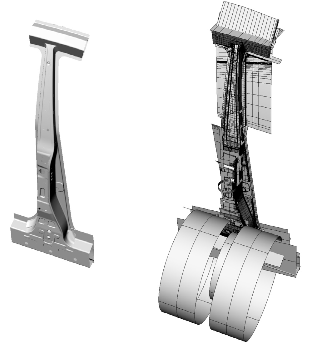
Figure 2. NURBS representation of a car’s B-pillar.
For example, as shown in Figure 2, the pillar between the two doors of the car is represented by NURBS. It looks simple and neat on the surface, but it is actually made up of 1537 NURBS curved pieces, of which 1276 pieces are trimmed. If you look at it after magnifying it, you will see that it is riddled with holes and extremely complicated. So, can these thousands of NURBS be merged into one without the need for splicing and trimming? The answer is yes, but more advanced theories and methods are needed.
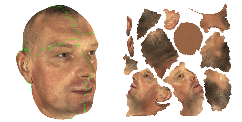
Figure 3. Traditional shard parameterization method.
As shown in Figure 3, traditional geometry processing software can only parameterize simple surface patches. For complex surfaces, traditional methods can only break them into multiple fragments and then tile each fragment onto a flat surface. In this way, many cracks inevitably appear on the three-dimensional surface, and it is very cumbersome and difficult to splice these cracks to ensure overall smoothness.
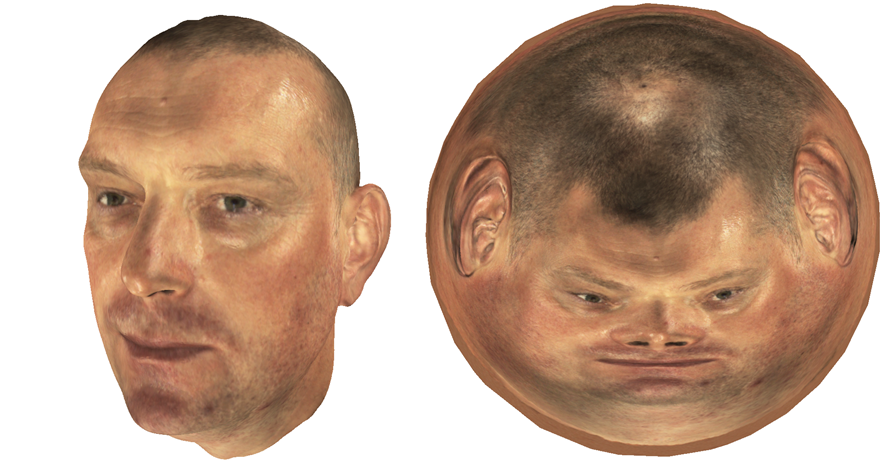
Figure 4. Global surface parameterization.
In our course, we have talked about the surface singularization theorem and Ricci flow theory. We know that the entire surface can be tiled onto a two-dimensional plane, thereby establishing the parameter domain of the surface. As shown in Figure 4, using Ricci flow and optimal transmission, we can parameterize the entire surface to avoid the splicing problem of the entire surface. For geometric modeling, we require overall structured quadrilateral mesh generation.
Advantages of the new approach
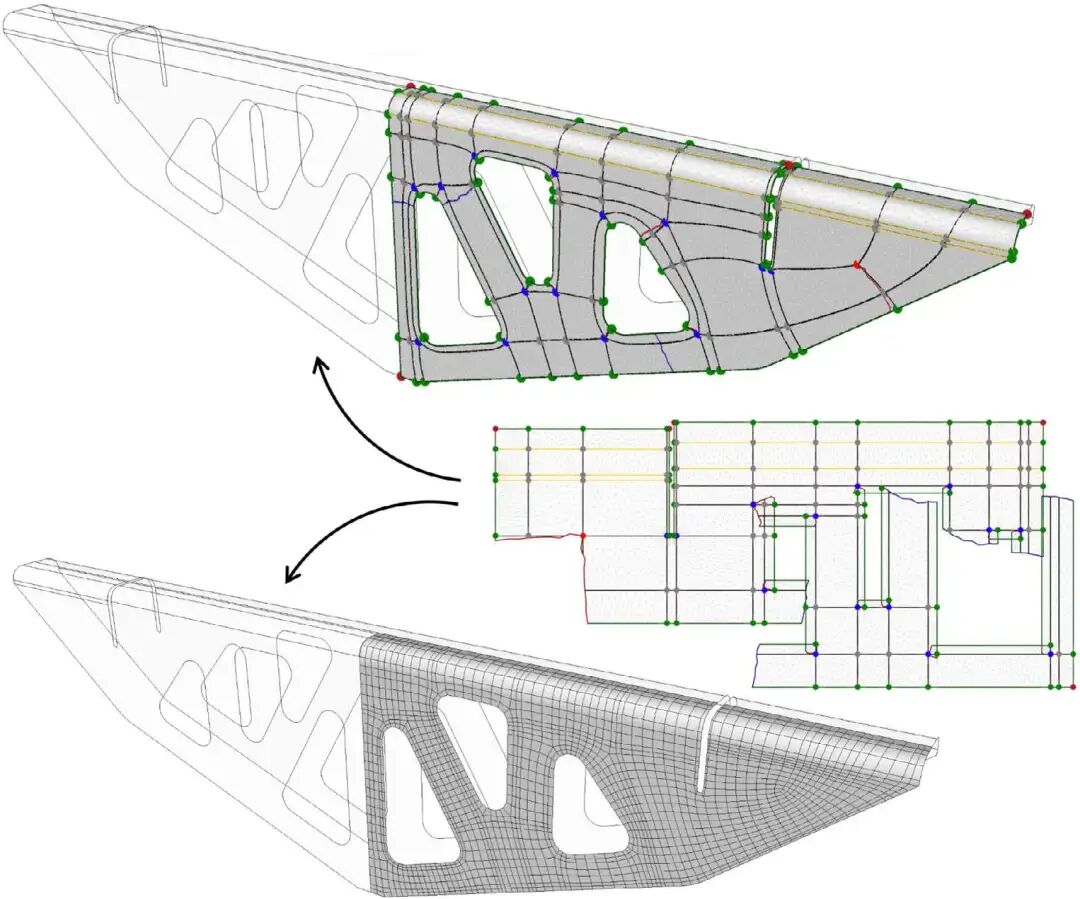
Figure 5. Structured quadrilateral mesh generation and singular point selection.
As shown in Figure 5, given a surface, which may have complex topology, we construct a structured quadrilateral mesh as a whole to generate high-quality NURBS. First of all, the grid lines of the grid are smooth and smooth, and the two families of manifolds are orthogonal and perpendicular to each other, which means that the streamlines are harmonic and conjugate, and the global parameterization of the surface is conformal. The key to integrity lies in the selection of the location of the singular point. If properly selected, the streamlines coincide with the characteristic lines and are parallel or perpendicular to the boundary. Locally, we can easily construct this kind of grid, but whether it can be expanded as a whole is a very interesting and profound question. This is also the core content of this summer course. Abel-Jacobi theory gives the limiting conditions of singular points, which determines the existence; Riemann-Roch gives how much is known, and the modern version of these theories is the cohomology theory of the pure line bundle cross-section layer.
Given a surface in the physical world with a Riemannian metric induced by Euclidean space, the surface has a natural conformal structure and can be regarded as a Riemannian surface. Representing the cotangent bundle of the surface, let the holomorphic line bundle be the 4th power of the cotangent bundle:
Equivalently, let be a holomorphic section of the cotangent bundle, that is, the holomorphic differential of the Riemann surface, be the divisor composed of zero points, let, then. If the quadrilateral meshing on any one is conformal, it corresponds to a meromorphic fourth differential, that is, a meromorphic section of . Given the user-specified singular points of the quadrilateral mesh, that is, the zero-pole configuration of , then we have:
All such meromorphic cross sections are equivalent to the holomorphic cross sections of the holomorphic line bundle, that is
The existence of a quadrilateral mesh therefore boils down to determining whether the cohomology group of the cross-section layer is zero. According to the Riemann-Roch theorem, the Euler characteristic number of the layer is:
Here g is the genus of the surface. Further by Serre's duality theorem
We face the following basic theoretical issues:
- Is there a quadrilateral mesh whose singular point configuration is exactly , which is equivalent to Is it an ordinary cluster? Is complex one dimension. This problem has been solved by using the fully pure differential algorithm, surface Ricci flow algorithm and Abel-Jacobi theory jointly invented by Mr. Qiu Chengtong and the author's team;
- If such a quadrilateral mesh does not exist, how to modify it , to ensure the existence of the quadrilateral mesh? This issue has been resolved;
- if It only partially describes the singular point configuration of the quadrilateral grid and estimates the size of the solution space, that is, the group of dimensions. This issue is currently open.
It can be known from the Riemann-Roch theorem that if we select a singular point that contains enough poles, that is, a singular point with degree 3 on the quadrilateral grid, then the right side must be a positive number and the solution must exist. This is consistent with experience: by adding singular points of degree 3, structured quadrilateral meshes are relatively easy to construct.
Compared with traditional methods, the method here has great advantages:
- The theory is rigorous, the entire algorithm has a strict theoretical basis, and the existence and uniqueness of the solution are guaranteed, making it universal;
- Automation, because mathematical theory is used to replace manual adjustments, the algorithm has a higher degree of automation;
- Holistic, the algorithm solves the problem as a whole, reduces the number of fragments and cracks, and improves the overall smoothness;
- Simplicity. In traditional spline modeling algorithms, the spline splicing of complex topology and the filling of holes at the intersection of multiple spline surfaces are very complex and cumbersome. The integrity of the new algorithm reduces the burden of splicing and is more concise and direct; at the same time, there is no longer complex pruning of the parameter domain (Figure 6);
- Applicability, the new spline surface is more suitable for back-end analysis tasks and path planning in CAM. This algorithm is also suitable for the conversion of surfaces obtained from topology optimization to NURBS, as well as geometric modeling using 3D scanning and reverse engineering methods.
In the long run, using the overall differential geometry perspective to abandon the local perspective is in line with the historical laws of scientific and technological development. From a recent engineering perspective, there are currently many unknowns that need further exploration, such as how grid streamlines conform to characteristic lines and boundary lines, etc. There is still a long way to go in this direction.
Figure 6. Traditional pruned NURBS (left frame); non-pruned overall NURBS (right frame)
Isogeometric analysis method
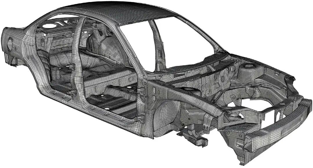
Figure 7. Traditional NURBS representation of the 1996 Dodge Neon CAD model, which cannot be used directly for IGA analysis.
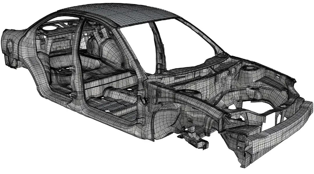
Figure 8. The Dodge Neon model after reparameterization based on global differential geometry can be directly used for isogeometric (IGA) analysis.
In the field of CAE, isogeometric analysis is currently a rapidly developing field. In the traditional geometric modeling (CAD) field, the mathematical representation of all models is spline surfaces; in the traditional CAE field, geometric models are represented by triangular meshes, and various partial differential equations are solved using finite elements, finite volume methods, etc. Converting CAD models into models suitable for analysis takes up about 70% of the entire process. The isogeometric analysis method unifies the mathematical representations of CAD and CAE and uses splines to express the solution space of partial differential equations, thus eliminating the intermediate steps of mesh generation and geometric approximation. Compared with the traditional finite element method, the isogeometric analysis method has certain advantages, such as smoother basis functions with better approximation capabilities, more accurate calculation results in resonance analysis, etc. However, NURBS surfaces in traditional CAD surfaces lack watertightness, and a large number of cracks, overlaps and other geometric defects make their NURBS representation unable to be used for isogeometric analysis (shown in Figure 7). The high-quality NURBS obtained using the method we introduce here can be directly applied to IGA to obtain high-precision calculation results (shown in Figure 8).
Summary
The traditional manual CAD modeling method first establishes spline representations of multiple surface patches, and then splices these surface patches together using Boolean operations and trimming. The resulting NURBS surface has a large number of cracks and local overlaps, and cannot obtain a watertight surface expression, so it requires heavy processing work to improve it. This method is essentially a partial method, rigidly spliced together in an engineering manner. If we use the theory of conformal geometry, we can use a global method to obtain the overall NURBS surface, which is watertight and directly suitable for downstream analysis and manufacturing processes. The core of the algorithm is the Ricci flow method and the cohomology theory of the fully pure line bundle cross-section layer. This once again shows the forward-looking and guiding role of modern mathematics in essential issues in the field of engineering.
Machine-translated from the Chinese original 传统CAD建模方法的瓶颈与整体微分几何 (published 2022-11-13). WeChat original ↗